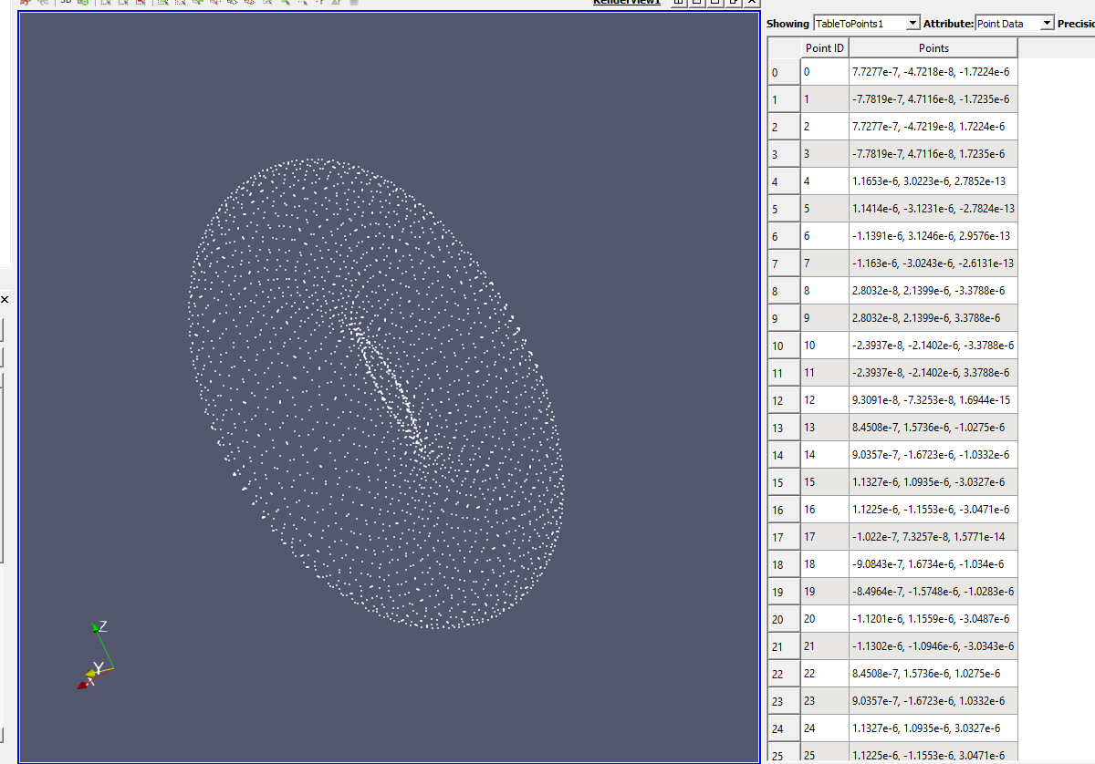


Whole extent may be thought of as the domain size for each direction. To make a structured grid, go to Filters → Alphabetical → Table To Structured Grid. Then, select the correct columns for x, y and z and fill in the correct values for Whole Extent. It also makes it a bit easier to interpret, as we get a complete, continuous geometry. Making a structured grid is not very different from single points, but because of ParaView's automatical interpolation, it is most often desired. If nothing shows up in the graphics window, click on it and then click on the eye next to points created under Pipeline Browser. Also, make sure the coloring of the points is set to differ from the background color. Then, select the correct columns for x, y and z and click Apply. To do so, go to Filters → Alphabetical → Table To Points. The easiest way to visualize your data is through single points. semi-colons, simply change the Field Delimiter Character under Properites (lower left in image below). If your file is not separated by commas, but by e.g. that the x-values are actually listed in the column named x256, z-coordinates in the column named z1 etc. To make it a bit more interesting, we will use example_2.csv which is attached in the section above. Then, click Apply, and a table should pop up. To import a file into ParaView, click Open or CTRL + O and located your file. Lastly, if we have some results we wish to add, simply insert them as an additional column. This is helpful knowledge when we later are to convert the points to a structured grid. Bailey's great tutorial on ParaView (see ParaView). They simply describe how many points there are in the current direction, thus for our box geometry of 3 x 3 x 1 nodes we get as shown above.

The numbers behind the x, y and z is something I picked up from Prof. So, when we later get into ParaView, we will not have to remember which column represented what, but rather just look at the descriptor. The top row in the example "x3 圓 z1" is in ParaView only used to describe the column, thus the values below.

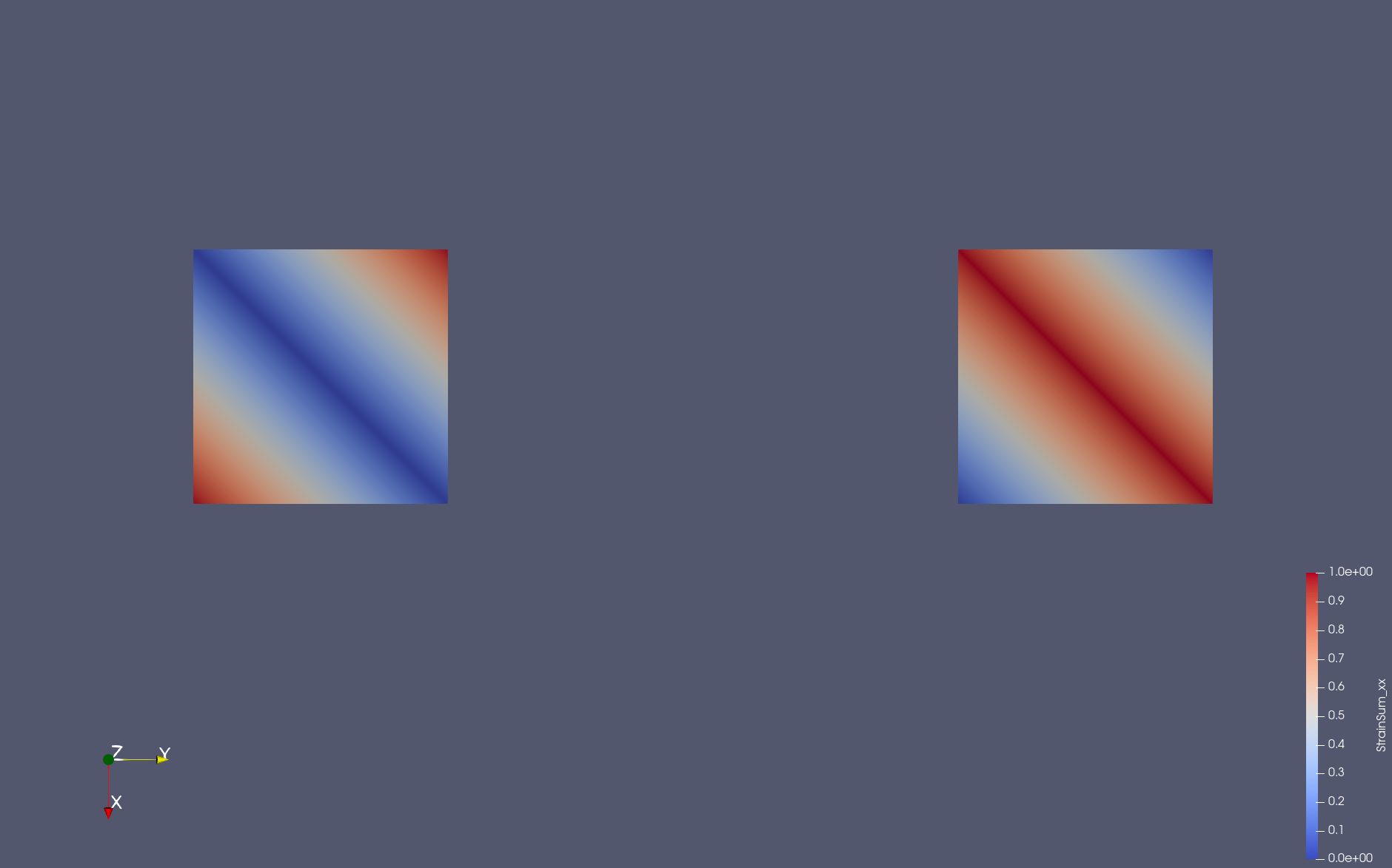
This is to not get any errors when importing into ParaView. As already mentioned, note that the x-values are the ones changing the fastest. Effectively, z = 0 is defined for all points. (The blue in between is just the resample filter trying to probe the empty space between your quadrilaterals.Although our chosen domain is in 2D, the function in ParaView that converts our table to a structured grid requires three coordinates. You can see that when a ParaView filter probes your data, you get the correct interpolation. So for example, in the following screenshot I have run the Resample To Image filter on your data. You are seeing the triangles the rendering system is interpolating on.Įven though the rendering system is simplifying your data, ParaView itself will do a proper bilinear interpolation. This is why you are seeing that either red or blue diagonal line through the squares. This is true for pretty much every OpenGL implementation I have encountered as well as the OSPRay rendering backend. This is because interpolating colors/texture coordinates is a lot faster for a triangle. Just about every rendering system will take quadrilaterals and internally divide them into triangles before rendering. The asymmetry you are seeing is an artifact from the rendering library that ParaView is using. ParaView is loading your data correctly, but rendering it a bit wrong. I just wanted to add a little clarity of what is happening.


 0 kommentar(er)
